KNX Topology Troubleshooting with ETS Tools
- KNX & ETS
- Published Apr 17, 2025
This article shows how to check your KNX installation’s topology with the tools provided by ETS. You can run through all the verifications from your desk without having to deal with the physical wiring.
KNX Basic Know-How
Before you start troubleshooting, make sure you understand the basics. The KNX Association has an excellent document that describes most of the important things in a concise manner. It’s available in English and German, for example.
I’ll briefly summarize the most important points relevant for smaller installations in the following sections.
Lines and Segments
- A KNX installation is comprised of lines that galvanically separate devices.
- A line can have up to 64 devices.
- Up to 15 sub lines can be branched off the main line 0 with line couplers.
- Each sub line (not the main line) can be extended with up to three repeaters which add segments of up to 64 devices each.
- Each line and each segment needs its own power supply.
Hop Count
- The KNX telegram hop count (also called routing counter) is similar to the TTL (time-to-live) in TCP/IP networks.
- The hop count prevents endless loops by limiting the maximum number of times a telegram can be forwarded.
- Each telegram starts with a hop count of six.
- Each line coupler, repeater, or router decrements a telegram’s hop count by one.
- When a telegram’s hop count reaches zero, it is not forwarded anymore.
Individual Addresses
- Each KNX device requires a individual address (also called physical address).
- The individual address is assigned through ETS after the device has been put into programming mode.
- The structure of individual addresses is:
x.y.zwhere:xdesignates the area (typically1in smaller installations with only one area).ydesignates the line (0for the main line,1through15for sub lines).zdesignates the device on the line (0through255).
- Addresses of line couplers always have a
zcomponent of0, e.g.,1.2.0for the line coupler that joins line two to the main line zero.
Common Topology Errors
Cabling
- The main line and sub line are physically swapped in a line coupler’s cabling.
- Two lines are physically connected (creating a short circuit).
Individual addresses
- A device’s individual address does not match the line it’s physically connected to.
- E.g., the device is connected to line 2 but has an address on line 1 (
1.1.x).
- E.g., the device is connected to line 2 but has an address on line 1 (
- The individual address of the ETS interface does not match the line it’s physically connected to.
ETS Devices and Project Diagnostics
To get started, I recommend to thoroughly check your project with the diagnostic wizards built into the ETS:
I won’t cover the above tools and checks in this article. Instead, I’ll describe some troubleshooting steps that aren’t part of the ETS diagnostics.
Topology Check With a Line Scan
The Diagnostics panel in ETS has a useful Line scan tool. Putting our knowledge of lines and telegrams into practice, we can verify if the physical topology of the KNX cabling matches the logical topology in ETS. The Line scan tool lists all existing addresses in a line by querying the individual addresses one by one. If a device answers the query, its individual address is added to the output along with some basic information about the device, and, critically, the hop count.
In a typical setup where ETS is connected via a tunneling address of 1.0.1 to the main line 1.0, the hop counts listed in the following sections are expected.
Main Line (1.0)
As there should be no coupler between the ETS and the devices on this line, the hop count should be 6 for all devices, e.g.:
- Area coupler or router (
1.0.0): hop count6 - Devices on the line (
1.0.x): hop count6
Sub Lines (1.1 … 1.15)
There should be exactly one line coupler between the ETS and the devices on this line. The hop count should be 6 for the line coupler and 5 for all other devices, e.g.:
- Line coupler (
1.1.0): hop count6 - Devices on the line (
1.1.x): hop count5
Topology Check With Line Coupler Filter Tables
Another way to check an installation’s topology - and a good way to verify assumptions after the line scan topology check above - is based on the filtering capability of the line couplers.
The procedure is simple: we block the forwarding of individual addresses in a line coupler’s parameters. With such a block in place, devices on the line must not be reachable anymore. This can be verified, for example, by instructing ETS to query a device for information. Such a query should fail. If it does not fail, the device is not physically behind the line coupler from the point of view of the ETS.
Practical Example
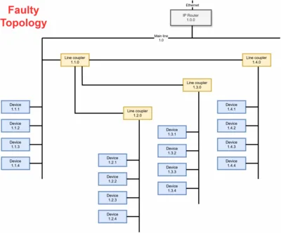
Consider the faulty topology depicted in the diagram at the top of this page.
Line Scan
When we perform line scans in ETS, we get the following results:
Line 1 (1.1)
- Line coupler: address
1.1.0, hop count6 - Device 1: address
1.1.1, hop count6 - Device 2: address
1.1.2, hop count6 - …and so on
The device hop count 6 proves that there is no line coupler between the router and the devices on line 1.
Line 2 (1.2)
- Line coupler: address
1.2.0, hop count5 - Device 1: address
1.2.1, hop count4 - Device 2: address
1.2.2, hop count4 - …and so on
The line coupler’s hop count 5 proves that there is a line coupler between the router and it - which shouldn’t be the case. The device hop count 4 proves that there is are two line couplers between the router and the devices on line 2. There should, of course, only be one.
Line Coupler Filter Tables
To verify our findings above, we can block the forwarding if individual address at the line coupler 1.1.0. With that block in place, the following ETS device query results should be observable:
- Query for
1.1.1: success - Query for
1.2.0: failure - Query for
1.2.1: failure
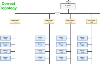
In the corrected topology shown in the diagram below, the query results would be:
- Query for
1.1.1: failure - Query for
1.2.0: success - Query for
1.2.1: success
Corrected Example Topology
The corrected topology from the diagram above would look as follows:


Comments